2003-(II)-Ultrasonic techniques - The Resonator
Article Index
Resonator cells 80 kHz - 20 MHz:
The ideal resonator
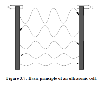
In order to understand the functioning of a real resonator, it is appropriate to take a look at the ideal resonator. In this work cylindrically shaped ultrasonic resonator cavities are operated in compressional modes. For the consideration of an ideal resonator some assumption have to be made. First, the ideal resonator consists of two piezoelectric planar transducers, separated by the distance l and with radius R . The wavelength of the sound waves is λ << R . As a consequence, plane waves are considered. Second, energy dissipation occurs only in the fluid.
Because of these assumptions it is possible to express the sound pressure at the receiver as a mathematical series:
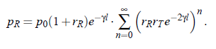
This series convergences for rR·rT < 1. With p T (0,t ) = p_ 0 ·eiωt this yields:
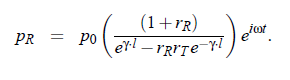
Finally, the transfer function T(f ) results as proportionality:
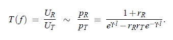
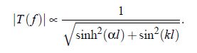
Its absolute value is:
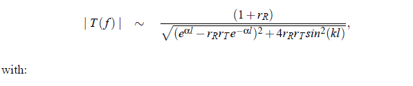
(index R denotes the receiver and index T the transducer)
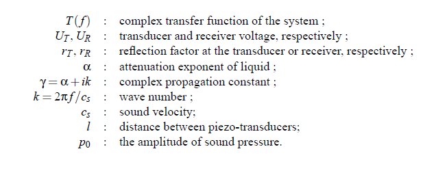
The transfer function for an ideal resonator with reflection coefficients at the liquid transducer interfaces rR = rT = 1:
With the relation sinh (γl) = sinh (αl) + sin (kl ), the amount of T (f ) is given by:
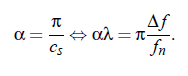
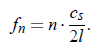
Consequently, for the ideal resonator equidistancy of resonance frequencies follows:
With the aid of the sound velocity of cs can be determined. For smaller losses, (α 1) Eq.(3.46) can be calculated with the use of Taylor series, at the resonances f n . For f = f n + δf the original value leads to the relation:
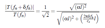
for the sound pressure. Consequently, the relation between the attenuation coefficient α and the half-power bandwidth ∆f = 2δf h follows as: