2003-(II)-Ultrasonic techniques - The Resonator
Article Index
The real resonator:
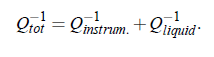
Quality factor the real resonator: In a real resonator, however, acoustic energy is not only dissipated by the liquid sample but also by imperfections of the cell. Among the various mechanisms is energy dissipation caused by diffraction of the sound wave due to the finite cell diameter. Furthermore, the radiative energy losses at the back face of the quartz, have also to be taken into account. The quality factor Q of a resonator is defined, by the ratio of reversibly stored energy and the dissipative energy. In summary, there are two contributions to the energy dissipation of a sound beam: attenuation caused by the liquid and that from the instruments. The total measured reciprocal quality factor can be written as:
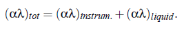
Because the quality factor Q is connected with the half-power bandwidth ∆f via: Q = f n /∆f and because of Eq.(3.50) the total attenuation per wavelength, can be expressed by:
Labhardt et al. have found a relation for losses of plane transducer resonators:
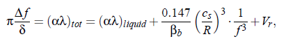
where βb = ZL /ZT , with the specific impedances of liquid ZL and transducer ZT. The second term on the right-hand side of the equation describes losses caused by diffraction of the sound beam, while V_r additional losses. However, it is not possible to analytically separate all instrumental loss contributions during measurements. Owing to this, it is necessary to perform a reference measurement, with a carefully chosen reference liquid with matched sound velocity and densit.
Transducer properties:
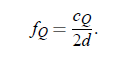
The resonances of the transducer can be expressed by the sound velocity of the transducer cQ and its thickness d:
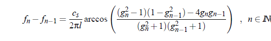
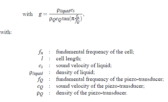
There is a finite liquid-to-transducer acoustical impedance ratio so that the sound can penetrate into the transducer. Caused by this effect, the cell-length ”seems” to be larger than the geometrical length. This effect becomes more important near the fundamental transducer frequency and its overtones. The cavity resonances are no longer equidistant. This behavior has been calculated by Labhardt, too:
In order to consider the influence of transducer resonance on the resonator transferfunction, a piezo-transducer transfer function E (f) has to be taken into account. Eggers and al. have proposed the function:
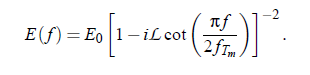
Here L is a factor, depending on the acoustic load and f T_m = f Q · m with m = 1,2,...,n.
Higher order modes:
At increasing frequency f and increasing attenuation coefficient α of the sample liquid, the resonances belonging to a principal mode of vibration of the cavity, will be more and more distorted and disturbed by undesired satellite peaks. The following equation expresses this behavior for the so-called biplanar-resonator:
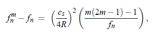
where f n denotes the frequency of the n-th principal mode, R is the cell radius and m is the number of the higher order satellite modes belonging to n mode (m = 1: principle mode). The distance between the resonance peak of a principle mode and a satellite peak depends on the geometry of the transducer. For the plano-concave resonator, with focussing effect of concavely shaped face of the circular cylindrical cavity resonator, follows:
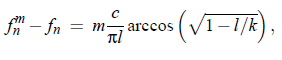
with k = radius of curvature of the concave face. Plano-concave resonator have been also used in this work (k = 2m). A favorable feature of such devices is the reduction of disturbances from mechanical stress during temperature variation, due
to the focussing effect. Other errors typical for measurements are caused by temperature fluctuations (change of c_s ), by changes in the geometrical dimensions of cell (due to cleaning, emptying or refilling procedures), errors of electronic equipment, especially of the impedance analyzer used for the transducer function measurements, and systematic errors due to insufficient parallel adjustment of the transducer crystals. In Table (3.1) one can find the instrumental data for relevant resonators of the present work and also some experimental errors: